|

HOME
NEW
CLICK HERE FOR AMAZON PRIME!
NEW CLICK HERE TO
SEND US A GIFT! A COOL IDEA TO HELP US FOR HELPING YOU!


| |
|
Build an All Band HF Air Core
1:1
Choke Balun
THE "UGLY BALUN"
A balun's purpose is to allow
connecting a BALanced
load (e.g., a dipole or driven element) to
an UNbalanced
line such as coax,
thus the name, Balun.
In transmitting antennas, this is accomplished by presenting
a high impedance (resistance), to RF currents flowing
outside the coax shield. This forces currents in each side
of a driven elements to be equal. This is especially
important in beam antennas because it prevents distortion of
the beam's pattern caused by unequal
currents in the driver(s). In a simple dipole, the balun
assures
that the dipole,
and not the feed line, is doing the radiating!
When you connect center fed antennas, like dipoles, V's,
triangles, yagis, rhombics, loops and so on, to coaxial
cable, unless care is taken, it is not difficult to end up
with feeder radiation. Not only
can
the loss in power be quite significant, but the radiation
characteristics of the antenna system will also be seriously
compromised.
In laymen's terms, it won't be what you are expecting from
the
pattern of your antenna.
As the feedline becomes part of the antenna, currents can
flow from the line into the mains and on TV cables, metal
masts and yagi booms, causing a variety of EMI problems
that can be very difficult to trace. Frequently these
problems are simply due to unbalance - and the solution is
the humble air choke 1:1 balun!
If an antenna system is fed at center with a parallel
conductor line (provided that correct installation
procedures are followed) balance will be maintained, USING A
BALUN, with currents in equal and opposite phase canceling
each other out.
When the
connection is to a coaxial cable, WITHOUT A BALUN, this
cannot occur because currents flowing inside the cable from
the connection to the inner conductor are separated from
those flowing on the outside from the connection to the
shield, and the result is unbalance causing feeder
radiation. However, if the two electrical circuit elements
(antenna and coaxial cable) are coupled using a balan,
balance will be maintained.
Enter.....The Ugly Balun!.....
An Inexpensive,
High-Performance,
Ugly
50 ohm Balun
"Building a no-grief 1.8MHz to 30MHz 50ohm-balun is easy.!"
"No
costly ferrite-cores are needed, just a short length of 3 to
5 inch size plastic pipe, about 25 feet of 50ohm coax plus
some nylon cable ties.
Solid-dielectric coax is best for this application because
foam-dielectric has a tendency to allow a change in the
conductor to conductor spacing over a period of time if it
is bent into a tight circle. This can eventually result in
voltage breakdown of the internal insulation.
The required length of the plastic pipe depends on the
diameter and length of the coax used and the diameter of the
pipe. For RG-213/U coax, about one foot of 5 inch size pipe
is needed for a 1.8MHz to 30MHz balun. For 3.5MHz to 30MHz
coverage, about 18 to 21 feet of coax is needed. This length
of coax is also adequate for most applications on 1.8MHz.
18 to 21 feet should cover all
of 160 through 10 meters.
The number of turns is not critical because
the inductance depends more on the length of the wire (coax)
than on the number of turns, which will vary depending on
the diameter of the plastic pipe that is used.
The coax is
single-layer close-wound on the plastic pipe.
The first and
last turns of the coax are secured to the plastic pipe with
nylon cable ties passed through small holes drilled in the
plastic pipe.
The coil winding
must not be placed against a conductor.
The name of this
simple but effective device is a choke-balun.
NOTE:
Some people
build choke-baluns, without a plastic coil-form, by
scramble-winding the coax into a coil and taping it
together. The problem with scramble-winding is that the
first and last turns of the coax may touch each other. This
creates two complications. The distributed-capacitance of
the balun is increased and the RF-lossy vinyl jacket of the
coax is subjected to a high RF-voltage. The single-layer
winding on the plastic coil-form construction method solves
these problems since it divides the RF-voltage and
capacitance evenly across each turn of the balun"....AG6K
Credit for this article goes to AG6K, Rick Measures and was
edited from a Pre-copy version of another article titled "A
BALANCED - BALANCED ANTENNA TUNER" published in QST,February,
1990.
"Ugly Balun" photos, ideas and
installations sent in by users!
Here are examples in the pictures below using cable ties on
PVC pipe forms which work well also. Your choice!
(Imagine the coil form is removed). Pictures are showing how
to secure the coils together. Do not let the first and last
coils touch!
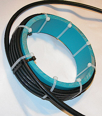
Picture above courtesy of VE7AVV
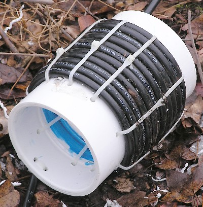
Picture
above courtesy of KC2NXV shows using 2 pvc couplers joined
and glued using about 2 inches of 4 inch PVC pipe, so the
couplers would adhere and be stronger.
More "Ugly Balun" ideas from DAVE
THOMAS, M3RUH BELOW:
The Dave Thomas, MW3RUH BOTTLE
SPECIAL!
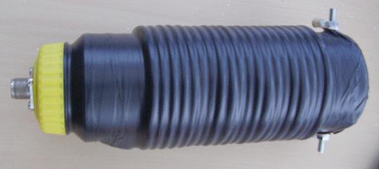
Dave uses a plastic drink bottle as a
form. He installs an
S0-239 in the bottle cap and antenna connectors on the other
end!
NICE TIP DAVE!
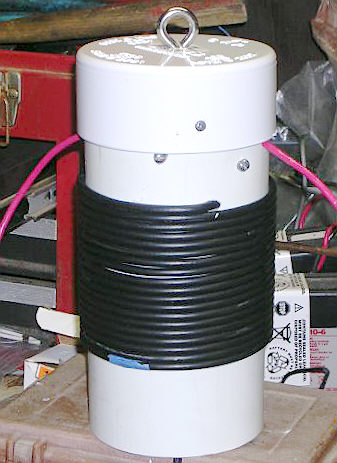 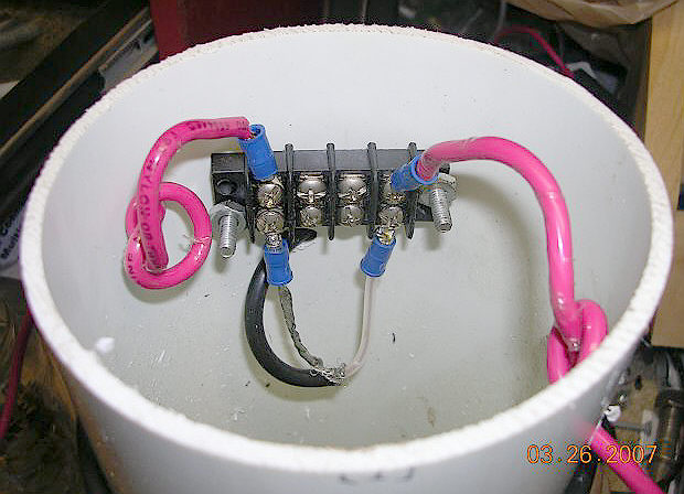
Photos courtesy Bill, KI4PCB,
using 4 " PVC FORM
Notice the screw terminal block used for connections
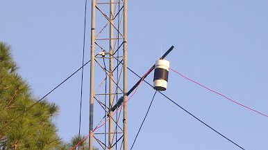
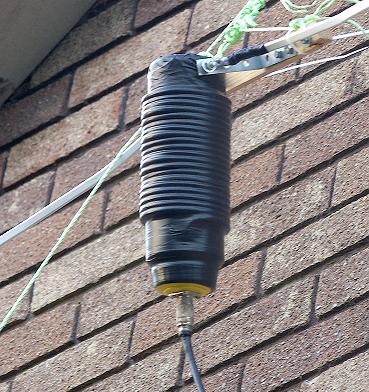
KI4PCB "Ugly Balun" on the air!
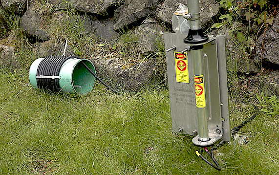
The N7ATA "Ugly Balun in Real
Life"...thanks Dan!
Notes from builders:
Email Concerning the "Ugly Balun"
From Russ Wilson
<ve6vk@telusplanetlnet>
"Don. I built one of the "Ugly Baluns".
I was using it on a dipole for 80/40 meters.
I had some TVI without the balun, so no doubt the feedline
was radiating.
With the balun attached, the TVI completely disappeared. I
built a second one as I had the same TVI problem with an R7.
The balun cured this as well. I can run my linear now with
no problems as all.
So I appreciate your expertise and your article."
"Thank you.
Best Wishes
Russ, VE6VK"
CHECK OUT
RUSS'S ANTENNA PROJECTS ON THIS SITE:
20 METER MINI BEAM
20 METER V BEAM
Photo Credit VE7AVV taken with permission from his project
at:
The TH6 Balun
Replacement Project
See the
rest of his site here!
MORE HERE SOON
|
|
|